
The broken plastic joint on a folding camping chair can be replaced with a 3D-printed one. I found a design at myminifactory that looks very similar to the one on my chair and tweaked it in Fusion 360 to match the dimensions needed. I printed a test piece to make sure it fits well, then fine-tuned the model further before printing it with 100% infill. I used regular black PLA filament on my Creality CR-10 printer.
Tuesday, August 9, 2022
Wednesday, August 3, 2022
Burnt / Darkened LCD Display Repair
A fairly easy way to repair such LCDs that are found in many common devices. I had used aluminum tape to replace the backing, but anything that can reflect a good amount of light, such as a piece of white paper should work too. I had also dipped the cotton bud in thinner to help with removing the adhesive, but any solvent of sufficient strength (such as nail polish remover) should work too. I've even seen others simply using an eraser to rub off the adhesive cleanly.
Sunday, June 21, 2020
A dead KitchenAid Diamond blender revived (Part 2 of 2)
Following a partial fix of the dead blender in Part One, I decided to get advise from the wonderful folks at Repair Kopitiam where I have been a part of for well over a year and a half now. Some of the volunteers there have many years of hands-on appliance repair skills so I thought they might have some useful tips on how to continue troubleshooting the power-tripping issue that I have been stuck with. I provided them with all the information on what I did in Part One, plus this picture of the power electronics side of the circuit board.

My own suspicion is that either one of the three components on the power board above might be damaged:
- X2 capacitor (yellow)
- BTA10 Triac (black, ST brand)
- 5V DC relay (Omron brand)
I am not formally trained in electronics so I have limited understanding of how these components work. My guess was solely based on my personal repair experience where I have successfully fixed a few dead devices/ appliances by simply replacing components of similar nature to these components above.
To determine if an electronic component is faulty, it would require removing the component from the board to measure its electrical properties with the multimeter. Taking measurements while it is still electrically connected to the board will not provide any certainty of whether it is good or bad. And removing a component from the board could be tricky as it usually requires desoldering it from the board, which could introduce unintended damage to nearby components (or even the component itself) if not done properly. I wanted to have more certainty that a component was likely damaged before resorting to removing it to check. Also, because if the removed component turned out to be good, there is the hassle of having to solder it properly back onto the board, which could again be tricky business. For these reasons, I decided I should seek advise from other experience repairers in my community before proceeding further.
I received the following four suggestions/guesses from several active members in the Repair Kopitiam community when I posted a message of my issue to them. Other than guess #4, I did not expect the others to point me back to areas that are not on the power electronics board. I also did not really think these were likely causes, but I proceeded to investigate them anyway.

The rationale behind this guess is that if there was some kind of braking device to stop the motor when powering it off, and that device was damaged, then the unexpected back EMF (ElectroMotive Force) could be triggering the power trip. So I carefully checked the structure of the motor and didn't find anything that looked like a brake on the motor. The only thing other than the motor's terminal that is connected to the circuit board was a small black component tucked under the motor's cooling fan blade. It was held in place by magnet forces and there is no label on it that can help me identity what it is for.


To determine if this component could have anything to do with the power trip issue, I detached it from its location on the motor then operated the blender. Here is the result -
The video shows an error status where all the button indicators blinked, once the motor tried to start up, and then no power would be supplied. Interestingly, there was no power trip. I had to refer to page 15 of the user manual to figure out what this error status mean -https://www.appliancesonline.com.au/public/manuals/KitchenAid-Diamond-Blender-KSB1585---Almond-Cream-User-Manual.pdf. Clearly, the component is some kind of sensor to detect the spin of the motor, possibly even an encoder as it has quite a number of wires connected to the circuit board. So the conclusion was: no braking system present in the blender that could be the cause of the power trip issue.

The EMI filter referred to here is the large metal box component that I checked for electrical continuity in Part One. I was only concerned with its electrical pass-thru (continuity) at the time as I was diagnosing for any breakpoints that could have prevented the blender from powering up. Now that it could power up, there might just be a possibility that the capacitors or inductors inside the EMI filter are faulty without affecting its ability to send power to the board. This is because most of the components in the EMI filter are connected in parallel to the power supply wires. as shown by the circuit diagram at the bottom of its label. So power could still be sent thru if any component connected in parallel was damaged.

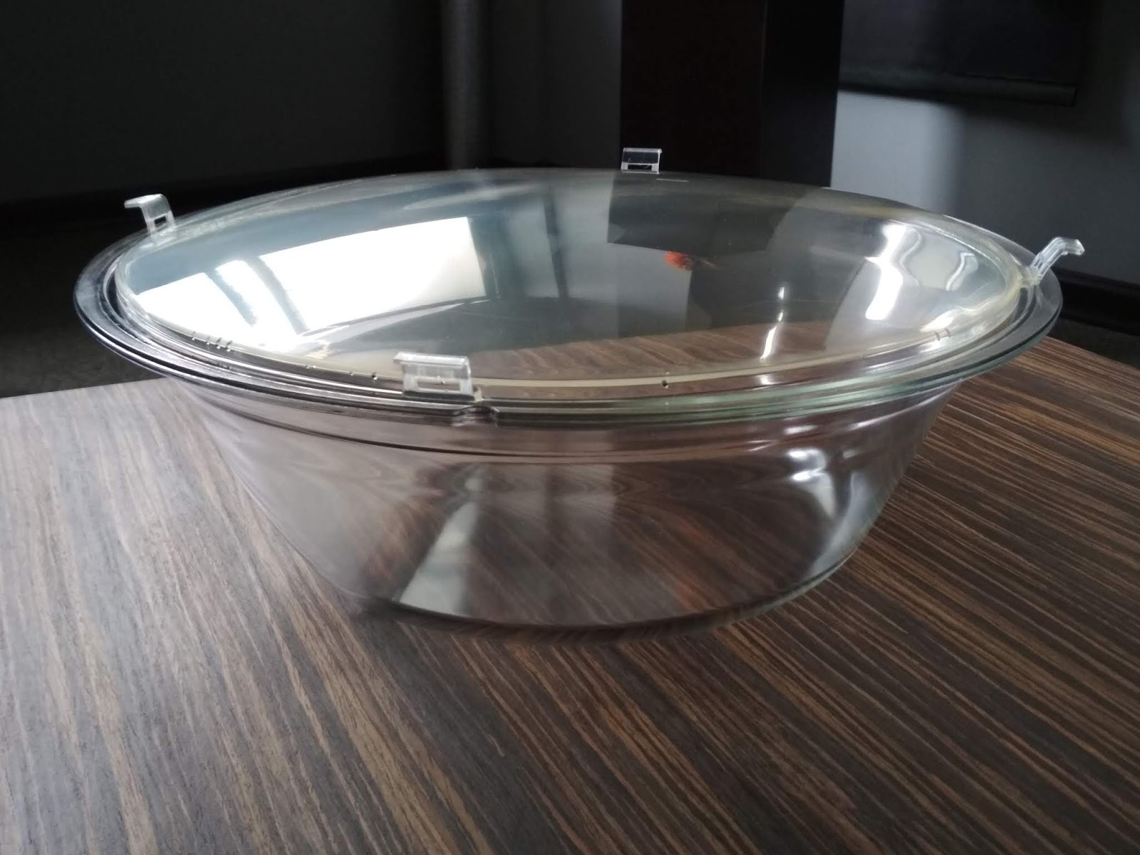
If this was the case, its inability to properly filter the back EMF as the motor spins down to a stop could be a reason for triggering the power trip. The multimeter that I have is only able to measure capacitance and resistance, but not inductance. I measured both capacitance and resistance between the top and bottom lines and found that both values are very close to the specifications stated on the label.


So I concluded that the EMI filter is in good working condition.

This is suggesting that the motor itself might be partially damaged somehow such that upon powering it down, it shorted itself and caused the trip. I was rather unwilling to do this test as I didn't see any point since even if it did trip my home breaker this way when powering down the motor, it could be that the motor has been designed to be operated with some other electrical components on the circuit board to avoid causing a back EMF to trip the circuit. So running it without the circuit board would not provide any useful information whatsoever, in my opinion as to why it would trip the circuit, not necessary that the motor is bad. Moreover, I had already tried powering off the blender using the AC wall switch after the partial repair in Part One. And that didn't result in any power trip. So doing it again with the electrical power bypassing the circuit board should logically not produce any different of an outcome. Eventually though, I still proceeded to verify this for my friends as they were simply too eager to know if it would trip this way (or maybe they were just eager to see me get an electric shock, haha).
I hooked up the connector of the motor directly to the AC output from the EMI filter using two short pieces of wire. To prevent the connection from coming off due to strong vibrations from the motor (yes this motor's gonna be quite a beast when it runs at its max rated power of 600W), I used a rubber band to hold the connection assembly in its place like this:

Then with one hand wearing an insulation glove (in case something breaks loose and electrically touches my hand) while holding the uncovered blender steady, I plugged it in and powered the beast up.
Well, the friends who suggested this to me were probably disappointed that nobody got shocked by what happened. :)
On to the last suggestion!

This is suggesting that a capacitor on the power board, likely the yellow X2 or a blue MOV capacitor could be damaged, leading to the board's inability to filter out any back induced EMF when the motor spins on its own to a stop during power off. This was something I had also suspected to be a possible culprit. However, I decided not to investigate any of the capacitors but instead look into the Triac.
The main reason I decided to investigate the Triac (I didn't know that's its name at first) was that the burnt copper trace that I had repaired in Part One was directly linked to one of the pins of the Triac.

But I didn't know how a Triac works, much less how to diagnose if it was damaged. So the next thing I did was to find its datasheet based on the marking on the component: BTA10-600BW.

From the datasheet (https://www.st.com/resource/en/datasheet/btb10.pdf), I extracted this important information from two of the pages.


Then I went researching on how to diagnose a Triac, how a Triac works, and what is meant by a "Snubberless" Triac.
Most of the Youtube videos I could find on diagnosing Triacs have verbal explanations in Hindi, which I cannot understand, haha. Fortunately, I found this one that uses on-screen texts to explain things - https://www.youtube.com/watch?v=VzywtlHry4g. After watching the video, I knew for certain that it is possible to use a multimeter to check if a Triac was damaged based on the conductivity characteristics between the pins. But I wanted to know more about what each pin is for so that I can have a better grasp of what I should be checking for. I searched online for how Triacs work and found this Youtube video to be particularly helpful in understanding the configuration of the 3 pins on Triacs and also what a Snubberless Triac means. https://www.youtube.com/watch?v=9He-d-IdRQY
The next step was to disconnect the Triac from the circuit board. I did not want to totally detach the Triac so that in case the test showed that it was not damaged, I would be able to reattach it back easily. The easiest way I could think of was to snip off the pins of the Triac near their bent locations. This would allow me to reconnect it back easily if necessary, by applying solder to where I had snipped open the pins.

After the pins were snipped, I checked for electrical conductivity between pins A1 & A2. Theoretically, with a good Triac, pins A1 and A2 should not be connected if the gate pin (G) is not triggered. But in the case of this Triac, I found that it was a closed circuit! This must mean that the Triac was damaged! I was eager to get a new Triac to confirm this, but upon checking with the local shops still in business at Sim Lim Tower during the Covid-19 lockdown, they do not have the same Triac I needed, although one of the shops did have the non-Snubberless version (ie. BTA-600 without the BW). It probably was too risky to try it so..
... it was online shopping time! :)
I found and ordered a bunch of BTA-600BW from this seller in China at https://www.aliexpress.com/item/32839985064.html It came in a pack of 5pcs per lot and so each piece was well under S$2. It took only 10 days to arrive, quite fast considering the free shipping and the Covid-19 situation at this time.

When I measured one of the new Triac that I received, between pin A1 and A2, it showed an open circuit as expected. So I was pretty confident this would restore the blender properly and proceeded to swap out the damaged Triac for a new one. This step was much more work than it would seem.
Firstly, I had to drill out the rivet that was securing the damaged Triac and its heatsink to the board.


My own suspicion is that either one of the three components on the power board above might be damaged:
- X2 capacitor (yellow)
- BTA10 Triac (black, ST brand)
- 5V DC relay (Omron brand)
I am not formally trained in electronics so I have limited understanding of how these components work. My guess was solely based on my personal repair experience where I have successfully fixed a few dead devices/ appliances by simply replacing components of similar nature to these components above.
To determine if an electronic component is faulty, it would require removing the component from the board to measure its electrical properties with the multimeter. Taking measurements while it is still electrically connected to the board will not provide any certainty of whether it is good or bad. And removing a component from the board could be tricky as it usually requires desoldering it from the board, which could introduce unintended damage to nearby components (or even the component itself) if not done properly. I wanted to have more certainty that a component was likely damaged before resorting to removing it to check. Also, because if the removed component turned out to be good, there is the hassle of having to solder it properly back onto the board, which could again be tricky business. For these reasons, I decided I should seek advise from other experience repairers in my community before proceeding further.
I received the following four suggestions/guesses from several active members in the Repair Kopitiam community when I posted a message of my issue to them. Other than guess #4, I did not expect the others to point me back to areas that are not on the power electronics board. I also did not really think these were likely causes, but I proceeded to investigate them anyway.
The rationale behind this guess is that if there was some kind of braking device to stop the motor when powering it off, and that device was damaged, then the unexpected back EMF (ElectroMotive Force) could be triggering the power trip. So I carefully checked the structure of the motor and didn't find anything that looked like a brake on the motor. The only thing other than the motor's terminal that is connected to the circuit board was a small black component tucked under the motor's cooling fan blade. It was held in place by magnet forces and there is no label on it that can help me identity what it is for.


To determine if this component could have anything to do with the power trip issue, I detached it from its location on the motor then operated the blender. Here is the result -
The EMI filter referred to here is the large metal box component that I checked for electrical continuity in Part One. I was only concerned with its electrical pass-thru (continuity) at the time as I was diagnosing for any breakpoints that could have prevented the blender from powering up. Now that it could power up, there might just be a possibility that the capacitors or inductors inside the EMI filter are faulty without affecting its ability to send power to the board. This is because most of the components in the EMI filter are connected in parallel to the power supply wires. as shown by the circuit diagram at the bottom of its label. So power could still be sent thru if any component connected in parallel was damaged.

If this was the case, its inability to properly filter the back EMF as the motor spins down to a stop could be a reason for triggering the power trip. The multimeter that I have is only able to measure capacitance and resistance, but not inductance. I measured both capacitance and resistance between the top and bottom lines and found that both values are very close to the specifications stated on the label.


So I concluded that the EMI filter is in good working condition.
I hooked up the connector of the motor directly to the AC output from the EMI filter using two short pieces of wire. To prevent the connection from coming off due to strong vibrations from the motor (yes this motor's gonna be quite a beast when it runs at its max rated power of 600W), I used a rubber band to hold the connection assembly in its place like this:

Then with one hand wearing an insulation glove (in case something breaks loose and electrically touches my hand) while holding the uncovered blender steady, I plugged it in and powered the beast up.
Well, the friends who suggested this to me were probably disappointed that nobody got shocked by what happened. :)
On to the last suggestion!

This is suggesting that a capacitor on the power board, likely the yellow X2 or a blue MOV capacitor could be damaged, leading to the board's inability to filter out any back induced EMF when the motor spins on its own to a stop during power off. This was something I had also suspected to be a possible culprit. However, I decided not to investigate any of the capacitors but instead look into the Triac.
The main reason I decided to investigate the Triac (I didn't know that's its name at first) was that the burnt copper trace that I had repaired in Part One was directly linked to one of the pins of the Triac.

But I didn't know how a Triac works, much less how to diagnose if it was damaged. So the next thing I did was to find its datasheet based on the marking on the component: BTA10-600BW.

From the datasheet (https://www.st.com/resource/en/datasheet/btb10.pdf), I extracted this important information from two of the pages.


Then I went researching on how to diagnose a Triac, how a Triac works, and what is meant by a "Snubberless" Triac.
Most of the Youtube videos I could find on diagnosing Triacs have verbal explanations in Hindi, which I cannot understand, haha. Fortunately, I found this one that uses on-screen texts to explain things - https://www.youtube.com/watch?v=VzywtlHry4g. After watching the video, I knew for certain that it is possible to use a multimeter to check if a Triac was damaged based on the conductivity characteristics between the pins. But I wanted to know more about what each pin is for so that I can have a better grasp of what I should be checking for. I searched online for how Triacs work and found this Youtube video to be particularly helpful in understanding the configuration of the 3 pins on Triacs and also what a Snubberless Triac means. https://www.youtube.com/watch?v=9He-d-IdRQY
The next step was to disconnect the Triac from the circuit board. I did not want to totally detach the Triac so that in case the test showed that it was not damaged, I would be able to reattach it back easily. The easiest way I could think of was to snip off the pins of the Triac near their bent locations. This would allow me to reconnect it back easily if necessary, by applying solder to where I had snipped open the pins.

After the pins were snipped, I checked for electrical conductivity between pins A1 & A2. Theoretically, with a good Triac, pins A1 and A2 should not be connected if the gate pin (G) is not triggered. But in the case of this Triac, I found that it was a closed circuit! This must mean that the Triac was damaged! I was eager to get a new Triac to confirm this, but upon checking with the local shops still in business at Sim Lim Tower during the Covid-19 lockdown, they do not have the same Triac I needed, although one of the shops did have the non-Snubberless version (ie. BTA-600 without the BW). It probably was too risky to try it so..
... it was online shopping time! :)
I found and ordered a bunch of BTA-600BW from this seller in China at https://www.aliexpress.com/item/32839985064.html It came in a pack of 5pcs per lot and so each piece was well under S$2. It took only 10 days to arrive, quite fast considering the free shipping and the Covid-19 situation at this time.

When I measured one of the new Triac that I received, between pin A1 and A2, it showed an open circuit as expected. So I was pretty confident this would restore the blender properly and proceeded to swap out the damaged Triac for a new one. This step was much more work than it would seem.
Firstly, I had to drill out the rivet that was securing the damaged Triac and its heatsink to the board.


With the old Triac removed, I could do a simple video below to directly compare how the pins on a good Triac and the damaged Triac behaved when probed with the multimeter set to the mode for testing electrical continuity.
Next, I had to find a bolt and a nut of the suitable size that can secure the new Triac and the heatsink back to the board.

Then I cleaned out the old thermal grease from the heatsink and applied new thermal grease to the back of the Triac.


Just before securing the parts back to the board, I also added a drop of thread-lock to the nut. This was necessary to prevent the vibrations by the powerful motor from slowly loosening the nut over time. It was probably the reason why the manufacturer originally used a rivet to secure the parts together as rivet mounted parts have no chance of being detached by such vibrations.

The new Triac then gets attached and the pins are soldered onto the leftover pins from the old Triac that are still connected to the board.

One final look at everything on the circuit board to ensure nothing was amiss before putting it back to the blender.
Once everything was back the way it was, the moment of truth!
Hooray! Let's try the Pulse mode.
How about the Ice-Crush mode? Hehe.
Finally, I can return the revived blender to its owner, and claim my reward. :P
PS. One thing I noticed here as compared to when it was only partially fixed in Part One, is that the sound of the motor spinning is audibly softer at the slower speed settings, whereas it sounded like it was running at the same speed regardless of whichever speed it was set to in the last video of Part One. This implies that the Triac works to control the speed of this blender. Another precious knowledge that I have learnt from doing this repair. :)
A dead KitchenAid Diamond Blender revived! (Part 1 of 2)
This is a documentation of what I did to investigate, diagnose, and eventually repair a dead blender. Below is Part One where I partially repaired it after some basic diagnostic checks. There was still a teething issue after this and I had to investigate further with more in-depth diagnostic techniques which I have documented in Part Two, where the steps leading to complete repair of the blender are explained.
Background: The blender is a KitchenAid Diamond Model 5KSB1585BAC and belongs to a friend. It has been in faithful service for about nine years before it just stopped working one day when in use. The power indicator LED did not even light up when power was switched on. So it was pretty much dead. I asked my friend to firstly check the fuse inside the power plug using a smartphone with this technique (cos she had no access to a multimeter) - https://www.youtube.com/watch?v=HGbHekFFuLg. The fuse was deemed ok and she removed the bottom of the blender in order to inspect the components inside. The base was simple to detach by simply removing four screws (two were partially hidden by rubber feet that popped out easily). A quick visual inspection of the insides didn't reveal any obvious signs of damage. So I took over the blender to diagnose further.


The first thing I did was to check the large rectangular metallic component (seen on the right side of the image above) for electrical continuity.

That component connects the mains AC inlet wires and then outputs power to the circuit board. I found out from the label on the component that it is an EMI filter, which is basically an assembly of capacitors and inductors across the power lines to filter out unwanted electrical noise signals. My thought was that perhaps it was damaged internally and so couldn't pass the AC power out to the circuit board. So I used a multimeter to check for continuity and it turned out to be good.
Next, I wanted to know if the motor was good. I was able to find this label pasted on the motor and it indicated it was an AC motor running on an AC voltage level that's the same as the mains voltage (i.e. 230V). It also rates the motor at 660W. Quite a beast of a motor for a blender! Typically, motors used in home appliances like blenders, fans, and vacuum cleaners are AC motors, which are brushless. This means that it is fairly easy to detect a damaged motor coil by simply checking for electrical continuity at the motor terminals (whereas in brushed DC motors, there are other possible reasons such as worn out brushes or a damaged commutator that can contribute to failed electrical continuity across the motor terminals).
I unplugged the motor from the circuit board and did the continuity test like this -
Typically, motors used in home appliances like blenders, fans, and vacuum cleaners are AC motors, which are brushless. This means that it is fairly easy to detect a damaged motor coil by simply checking for electrical continuity at the motor terminals (whereas in brushed DC motors, there are other possible reasons such as worn out brushes or a damaged commutator that can contribute to failed electrical continuity across the motor terminals).
I unplugged the motor from the circuit board and did the continuity test like this -
If the electrical continuity test on the AC motor had failed, I would have had to remove the motor to look for what is known as a thermal fuse connected to it which could have blown (due to overheating) or if the problem was caused by a burnt wire somewhere in the motor's wire coil. Replacing a blown thermal fuse could be easy or hard depending on where it is embedded. But a burnt motor coil would mean there's no way to repair the mote and at the point, it would be time to search for a replacement motor and it could be the most expensive spare part of the appliance. So thankfully this wasn't the case. It was also not easy to detach the motor from this blender after I tried to, so I was glad to be spared of this ordeal.
Moving on, the only thing left for me to investigate was the circuit board.
At this juncture, I was quite convinced that the electronics is the problem and there are only two possible ways to successfully repair this blender-
1. The exact electronic component(s) on the circuit board that is(are) faulty can be found and can be replaced.
2. Purchasing the entire circuit board assembly as a spare part to replace it.
I unplugged the motor cables, the power supply cables (coming from the EMI filter, the large metal box component I test earlier) before trying to remove the control panel assembly. I also had to detach a small black component (no marking on it) held in place by magnet forces under the fan of the motor, as it is permanently secured to the circuit board. I suspected it could be some kind of hall sensor to check for the rotation of the motor.

It was tricky removing the whole control panel assembly as the motor was getting in the way, but after some careful prying, the entire assembly (which included the button panel) was detached.

A few screws had to be removed to separate the plastic housing, and then two distinct circuit boards can be seen - one for the power electronics and the other for the control panel electronics, both linked to each other by five exposed and uninsulated wires.


I wasn't able to see any damaged component on the boards at first, but upon closer inspection at the back of the boards, I noticed some kind of burnt mark and it seemed like something has dropped away from the board due to the burnt.

Using a magnifier app on my phone to zoom in really close, it became clear that the missing part that had been burnt off was not a component, but a small section of the copper trace!

I have never encountered such a fault before, but it was good news because all I needed to do was to bridge the broken trace with a piece of wire.
So I soldered a suitable wire across two existing solder points found on each side of the broken trace and then quickly assembled the circuit boards back into the blender and proceeded to test the blender immediately.

I was very excited that the power indicator LED lit up when I pressed the power button! And then I pressed the various mode buttons and they all seemed to be working too. Hooray! I thought it was a success.... but my excitement was short-lived (watch the video below to see what happened at the end of the test). :P
The blender tripped my home's main circuit breaker whenever it got powered off. Even when trying out the pulse mode or the ice crushing mode, where the motor has to stop temporarily, it would trip my home's circuit breaker too. Dang!
Background: The blender is a KitchenAid Diamond Model 5KSB1585BAC and belongs to a friend. It has been in faithful service for about nine years before it just stopped working one day when in use. The power indicator LED did not even light up when power was switched on. So it was pretty much dead. I asked my friend to firstly check the fuse inside the power plug using a smartphone with this technique (cos she had no access to a multimeter) - https://www.youtube.com/watch?v=HGbHekFFuLg. The fuse was deemed ok and she removed the bottom of the blender in order to inspect the components inside. The base was simple to detach by simply removing four screws (two were partially hidden by rubber feet that popped out easily). A quick visual inspection of the insides didn't reveal any obvious signs of damage. So I took over the blender to diagnose further.

The first thing I did was to check the large rectangular metallic component (seen on the right side of the image above) for electrical continuity.

That component connects the mains AC inlet wires and then outputs power to the circuit board. I found out from the label on the component that it is an EMI filter, which is basically an assembly of capacitors and inductors across the power lines to filter out unwanted electrical noise signals. My thought was that perhaps it was damaged internally and so couldn't pass the AC power out to the circuit board. So I used a multimeter to check for continuity and it turned out to be good.
I even confirmed that it was able to output AC230V when I power up the 3-pin plug.
Next, I wanted to know if the motor was good. I was able to find this label pasted on the motor and it indicated it was an AC motor running on an AC voltage level that's the same as the mains voltage (i.e. 230V). It also rates the motor at 660W. Quite a beast of a motor for a blender!
 Typically, motors used in home appliances like blenders, fans, and vacuum cleaners are AC motors, which are brushless. This means that it is fairly easy to detect a damaged motor coil by simply checking for electrical continuity at the motor terminals (whereas in brushed DC motors, there are other possible reasons such as worn out brushes or a damaged commutator that can contribute to failed electrical continuity across the motor terminals).
I unplugged the motor from the circuit board and did the continuity test like this -
Typically, motors used in home appliances like blenders, fans, and vacuum cleaners are AC motors, which are brushless. This means that it is fairly easy to detect a damaged motor coil by simply checking for electrical continuity at the motor terminals (whereas in brushed DC motors, there are other possible reasons such as worn out brushes or a damaged commutator that can contribute to failed electrical continuity across the motor terminals).
I unplugged the motor from the circuit board and did the continuity test like this - If the electrical continuity test on the AC motor had failed, I would have had to remove the motor to look for what is known as a thermal fuse connected to it which could have blown (due to overheating) or if the problem was caused by a burnt wire somewhere in the motor's wire coil. Replacing a blown thermal fuse could be easy or hard depending on where it is embedded. But a burnt motor coil would mean there's no way to repair the mote and at the point, it would be time to search for a replacement motor and it could be the most expensive spare part of the appliance. So thankfully this wasn't the case. It was also not easy to detach the motor from this blender after I tried to, so I was glad to be spared of this ordeal.
Moving on, the only thing left for me to investigate was the circuit board.
At this juncture, I was quite convinced that the electronics is the problem and there are only two possible ways to successfully repair this blender-
1. The exact electronic component(s) on the circuit board that is(are) faulty can be found and can be replaced.
2. Purchasing the entire circuit board assembly as a spare part to replace it.
I unplugged the motor cables, the power supply cables (coming from the EMI filter, the large metal box component I test earlier) before trying to remove the control panel assembly. I also had to detach a small black component (no marking on it) held in place by magnet forces under the fan of the motor, as it is permanently secured to the circuit board. I suspected it could be some kind of hall sensor to check for the rotation of the motor.

It was tricky removing the whole control panel assembly as the motor was getting in the way, but after some careful prying, the entire assembly (which included the button panel) was detached.

A few screws had to be removed to separate the plastic housing, and then two distinct circuit boards can be seen - one for the power electronics and the other for the control panel electronics, both linked to each other by five exposed and uninsulated wires.


I wasn't able to see any damaged component on the boards at first, but upon closer inspection at the back of the boards, I noticed some kind of burnt mark and it seemed like something has dropped away from the board due to the burnt.

Using a magnifier app on my phone to zoom in really close, it became clear that the missing part that had been burnt off was not a component, but a small section of the copper trace!

I have never encountered such a fault before, but it was good news because all I needed to do was to bridge the broken trace with a piece of wire.
So I soldered a suitable wire across two existing solder points found on each side of the broken trace and then quickly assembled the circuit boards back into the blender and proceeded to test the blender immediately.

I was very excited that the power indicator LED lit up when I pressed the power button! And then I pressed the various mode buttons and they all seemed to be working too. Hooray! I thought it was a success.... but my excitement was short-lived (watch the video below to see what happened at the end of the test). :P
It wasn't a repair success at this point but at least I confirmed that the motor is still working well and the control panel are in good order. What could be causing the power trip? I continue in Part Two of the repair, where further in-depth diagnostics were made, with some interesting suggestions from friends at Repair Kopitiam, a local community of repair enthusiasts. Head over to Part Two now!
Monday, January 21, 2019
Part One: Salvaged Parts from Samsung Washing Machine WD0704CQQ

On 1st Jan 2019, I decided to disassemble my washing machine that had failed a few weeks before. I was not able to diagnose the cause of failure and it would cost too much to pay for Samsung's tech service just to come to tell me what was wrong. As I was curious to see how many interesting or useful parts I could find in it, I chose not to simply trash the entire thing away.
Besides the dozens of screws, bolts, nuts, and washers which can be reused, I found a whole bunch of other items that have the potential to be repurposed or used as parts in a project build.
1. Pressure Switch

This part detects the water level in the drum to control the inflow of tap water into the washing machine.

Close up inspection reveals the part number of the switch http://applianceoasis.com/shopping/dn-s14t-samsung-washer-water-pressure-switch/
2. Inductor Coil

I found this plugged into the power control board, which has been discarded into the e-waste bin.
Similar to this:
https://www.aliexpress.com/item/Wuxi-SEG-EI48-20-30W-inductor-coil-DC26-00009D-current-3A-inductance-8-5mH/32807022086.html
Similar to this:
https://www.aliexpress.com/item/Wuxi-SEG-EI48-20-30W-inductor-coil-DC26-00009D-current-3A-inductance-8-5mH/32807022086.html
3. Water Inlet Valve


4. Noise Filter

Definitely not for making the washing machine turn more silently. :)
5. Drain Pump Assembly


6. Electronic Control Board

Lots of tack switches, a loud buzzer, a rotating dial selector, and maybe the number display could be removed for other electronic projects.
7. Ceramic Heater

This is a 2000W heater element that seems to be coated in ceramics. Have already given this away.
8. Direct Drive Motor

I could get well over 40VAC from it when the motor is turned by hand if I spin it fast enough. See how bright it powers an AC LED bulb in this clip - https://www.youtube.com/watch?v=OR5Mc-1kYyQ
https://www.youtube.com/results?search_query=direct+drive+washing+machine+motor+generator
https://www.youtube.com/results?search_query=direct+drive+washing+machine+motor+bicycle
This is the end of Part One. See an even more interesting list of parts in Part Two, especially the mechanical parts in the latter half of the list there.
Part Two: Salvaged Parts from Samsung Washing Machine WD0704CQQ
This post is a continuation of Part One. If you are only interested to see the non-
electrical parts, scroll to item #14 onwards.
electrical parts, scroll to item #14 onwards.
9. Condenser Dryer Evaporation Unit


10. Evaporation Heater Element


11. DC Motor


Close up shows that it uses 608 ball bearings instead of bushings. A sign of good quality motor build, unlike many of the motors used in cheap home fans these days.
12. Sealed Thermostats

Two pieces of these were found in the Condenser Dryer Evaporation unit (item #9).
Specs of such thermostats - https://www.calcoelectric.com/images/pdfs_thermostats/calco_ksd301series.pdf
See how they work- https://www.youtube.com/watch?v=8245v9Q0xnI
13. Temperature Sensor (Thermistor)

Nothing more to say about this simple sensor except that it is probably a useful sensor for many IOT projects.
14. Flexible Rubber Hose Connectors

Various sizes and all come with quality clips. Easy to reuse them in gardening or plumbing projects.

15. Pair of Spring Coils

These coils suspend the weight of the entire drum and its contents. My unscientific testing shows that each spring takes about 50kg to stretch to twice its length. Pretty strong. Might be good for building a suspension chair or something like that.
16. Metal Drum

17. Steel Frame Body & Back Cover


With some plywood and a little creativity, I could see this being turned into a unique storage cabinet or some form of pet house.
18. Door Frame

 The glass dome has been removed (see next item). The shiny chrome finish of rim is maintained and the hinge still works. Can easily be made into a round window by inserting a piece of flat glass.
18. Door Frame

 The glass dome has been removed (see next item). The shiny chrome finish of rim is maintained and the hinge still works. Can easily be made into a round window by inserting a piece of flat glass.

Glass Door
Plastic Shield
20. Twelve Kilograms of Solid Cast Iron Encased in Plastic

Comes in 2 pieces of 6kg weight. Not exactly the best shape to use like a dumbell. but should be more usable once ropes or straps are attached to the existing holes found on them. Most likely I will make them into a weighted vest, which isn't exactly a cheap item to buy from the store.
https://www.decathlon.sg/p/8313278-3053-10-kg-weight-training-weight-gilet.html

These weights were originally attached towards the front of the washing machine to provide added stability. Now you know why a washing machine is so heavy!
That's all folks! If you haven't checked out Part One of the list, you should go there now, especially if you are into electronics and electrical stuff.
Subscribe to:
Posts (Atom)